This entry will cover the computation of power in ResSim. For this model, we have a single stream that contains one reservoir. I put in one outlet, a power plant, at the dam. In this simulation, I have 5,000 cfs coming into the model at the upstream end (CP1 is upstream end). The simulation starts with the pool at the top of conservation and maintains that elevation throughout. In other words, inflow = outflow at each time step.
The figure below shows that model schematic.


The figure below shows that model schematic.
The next figure shows the outlets. You can see that the only outlet is a power plant.
The power equation is as follows:
Power in megawatts (mw) = Q*w*h*e/737,560
where Q is in cfs, w is weight of water in lb/ft^3, h is head differential in feet, e is efficiency
Note that 737,560 ft-lbs/sec = 1 megawatt
Understanding the variables that go into the power equation will help with the understanding of the tabs used to describe the power plant.
The outlet tab specifies the hydraulic capacity of the power plant. In this case, the hydraulic capacity is set to 5,000 cfs for all elevations.
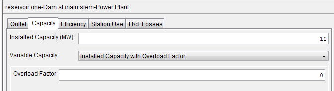
The capacity tab specifies the generating capacity of the power plant. The purpose of this tab is to limit the computed power generation to no more than the actual generating capacity. In this case, I set the maximum generating capacity to 10 mw.
For the efficiency tab, I set the value to a constant 80%.
Station use is for internal use at the dam. This value is often set to zero; however, I put in 500 cfs to show its impact. The value that is used for station use is passed through the outlet, but it is not used in the power computation.
The final tab is hydraulic losses. This reflects the losses associated with the power plant. The amount used for hydraulic losses is subtracted from the total head difference computation. For this example, I used a constant loss of 2 feet.
The head differential is computed as the difference between the headwater and tailwater. The headwater is computed as the pool elevation at each time step. For this simulation, the top of conservation (50 ft) is held for the entire simulation. For ease of computation, a constant tailwater elevation of 25 ft is used. This leads to a head differential of 25 ft.
The figures below show the top of conservation elevation and the tailwater definition.
The next figure shows the pool elevation and outflow results at the reservoir. Note that the pool elevation is held constant at 50 ft while the outflow is held constant at 5,000 cfs. Recall that there is only one outlet so all outflow is going through the power plant.
The power computation at all time steps is as follows:
Q = 5,000 - 500 = 4,500 cfs (note that 500 cfs is subtracted due to station use)
w = 62.4 lb/ft^3
h = 25 - 2 = 23 ft (2 is subtracted due to the hydraulic losses)
e = .80
Power (mw) = (4,500 * 62.4 * 23 * .80) / 737,560 = 7 mw
Since the generating capacity of 10 mw is not exceeded, the computed generation amount of 7 mw will not be limited.
The power generation plot is shown below. The upper plot shows a constant 7 mw of power generation. The bottom plot shows 5,000 cfs flowing through the power plant with 4,500 cfs of that flow used for power generation.
Hi Mr. Kavin. Thanks for this blog, it's very usefull for us.
ReplyDeleteI am modeling a hydroelectric power plant, located in an irrigation dam. Therefore, it is limited to the rules or irrigation demands.
For this I considered an installed capacity of 80 MW, with an overload factor 1, tailwater fuction of release, Also headloss.
As a result the discharged flow rate is highly variable, also the reservoir level (as I suppose), but the power remains constant at the installed, which is no true, because power depends on Q and H.
What am I doing wrong?. What do you recommend?.
Regards
Nico
I am not exactly sure of why you continue to get the same amount of power generated at each time step. The only thing that comes to mind is that the computed capacity for each time step exceeds the generating capacity and is therefore being limited to the installed capacity. You can look at your variables at each time step and enter them into the power equation to see if that is the case.
DeleteHello again, do you know what's the difference beteewn "Power Plant Flow" and "Power Plant - Flow QPOWER"?.
ReplyDeletethanks
Hello again, do you know what's the difference beteewn "Power Plant Flow" and "Power Plant - Flow QPOWER"?.
ReplyDeletethanks
hello sir , i want to run a simulation model for hydro electric project using the time series data inflow how to go it my Full reservior level is 1040m and minimum drawn down level is 1010m and the power outlet at 231 m and design disharge of 33 cumecs of installed capacity 210 mw and the discharge in a year range from 1 cumec to 2000 cumecs how to start
ReplyDeleteAs I have time, I plan to develop more posts dealing with power generation in ResSim. For your situation, it sounds like you have a power pool from 1,040 m to 1,010 m. You would specify that zone as your conservation zone if it is used for power. If you specify any part of that as the flood zone, ResSim will release water up to the physical capacity of all outlets unless you have other rules that would constrain it so you wouldn't have the control of when to release the water for power if it goes above the conservation zone. You can then specify a desired power generation pattern using a rule in ResSim (this is one of the posts that I need to develop). For the power plant, you would specify the physical parameters in the physical tab of the reservoir. If 33 cumecs is the physical release capacity, then that would be entered for the hydraulic capacity. It looks like you also have a 210 mw capacity. You also need to enter efficiency data for ResSim to be able to compute the power. I believe you are indicating that the inflow is between 1 cumec and 2,000 cumecs. If you are in the conservation zone, ResSim will store water when you are not requesting power generation or a minimum release or when the inflow exceeds these requests. Once you are above the conservation zone, ResSim will release up to the physical capacity of all outlets to bring it back down to the top of the conservation zone.
Deletehello sir i want to run a reservoir simulation by annexation a hydro-power plant to existing dam which supply water for irrigation, i would like to use the release for irrigation in order to generate hydro power, i'm wondering how i can integrate the hydro power plant on the outlet which supply water for irrigation.
ReplyDeletethanks
hi my name is bilal.
ReplyDeleteMy question is what is the range of outlet capacity factor use in the simulation model.
Please guide me in this regard.